A nice day to carry out air cooled chiller maintenance at a new site we have taken over in the South East.
News Article No.6
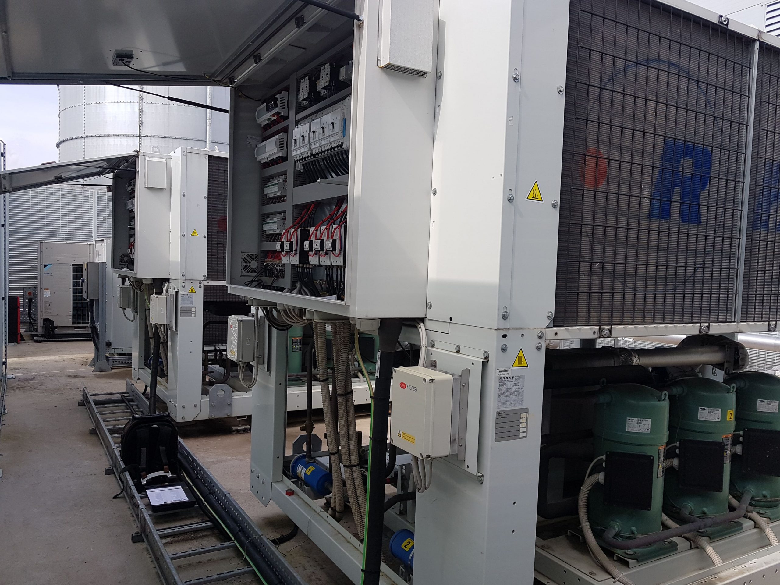
Our engineer attended site at around 9am with the risk assessment method statement having been sent in advance. A site survey was carried out to see if there were any additional risks. Should there have been any changes- the RAMS have a section for the additional risks and control measures. After gaining a permit to work, our engineer was issued with a security pass to access the chiller compound. Three chillers are located in the compound which feed air handlers for a critical application. Two of the chillers are multiple system, scroll compressor, air cooled chillers. The other is a single system screw chiller.
Program Settings during Air Cooled Chiller Maintenance
A complete download of the program settings is available in our engineer’s phone. This is to cross reference the settings, should one of them be accidentally changed by the maintenance engineers. On site engineers are the first port of call for chiller trip outs, with the responsibility to get the plant up and running. We offer real time assistance, over the phone from our Technical Support Desk and can send user manuals in PDF form, direct to their computer. The settings were found to be nominal, so a detailed analysis of the alarm history was carried out:
Alarm History during Air Cooled Chiller Maintenance
In reverse date order, the alarm history of all the systems was interrogated. There had been several system shut downs to carry out the periodic maintenance by the onsite personnel. The electricity having been shut down, there was a subsequent oil pre heating timer in the history too. On Chiller 2, System 1 however, there had been several low pressure trip outs. Our engineer decided to start the maintenance with this system by carrying out a full diagnosis of the low side of the refrigerant system:
0161 237 3727
service@maximuschillers.com
Superheat during Air Cooled Chiller Maintenance
The system runs on R410a refrigerant. This refrigerant has higher operating pressures in comparison with other HFC refrigerants. It has an efficient temperature range which can be seen on a pressure enthalpy chart. Below or above this range- the refrigerant loses efficiency and so has a lower coefficient of performance. The most common saturation point for this refrigerant is 0°C which corresponds to a 7 bar suction pressure in the evaporator. Above this is the superheat of the refrigerant returning to the compressor. On this occasion there was found to be 26°C of superheat and a suction pressure of 4 bar- close to the low pressure trip out. After careful diagnosis, our engineer decided to focus his attention on the expansion valve:
Thermostatic Expansion Valve
There are 4 forces acting on a TEV:
Liquid line pressure coming from the condenser.
Versus
Suction pressure down the equalising line from the far side of the evaporator. This compensates for the pressure drop across the evaporator and shows the true compressor side pressure.
Spring pressure acting upwards and closing the valve.
Versus
Bulb pressure forcing the valve open.
To reduce the superheat, the bulb should have forced the valve open. The refrigerant charge in the bulb acts upon the bellows to achieve this. The reason for the malfunction, on this occasion, was found to be the failure of the expansion valve orifice. It had become jammed- causing a shortage of refrigerant in the evaporator and high superheat.
Latent Heat
Our engineer was carrying out the above fault finding with one compressor running and the other two being held off. This was to prevent a low pressure trip. Where chillers are left running with a high superheat condition, the reduced amount of latent heat causes a higher cost in electricity relative to refrigeration effect (COP) The refrigerant carries on superheating without absorbing latent heat- pointless and inefficient for a chiller.
Chiller Pump Down
For convenience, this chiller can be pumped down and valved off using the service valves. The evaporator can be worked on after breaking in procedures are carried out. Therefore, we have arranged for this to be carried out before fitting the new expansion valve parts. These chillers also have the ability to pump down the refrigerant on receiving a fault feedback from the electronic leak detector. This is an added measure to lower the environmental impact of refrigerant leaks.
0161 237 3727
service@maximuschillers.com
Subcooling during Air Cooled Chiller Maintenance
This is cooling the refrigerant vapour down, through the latent heat phase and then subcooling the liquid down further. On System 2 of the same chiller, a subcooling issue was identified. 21 bar/ 36°C saturation was normal for that system as defined by the fan speed controller. Now, the system pressure was higher at 28 bar/ 47°C saturation, so our engineer decided to work out the subcooling. A very high reading of subcooling was recorded at 28°C this was diagnosed to be due to non condensables in the refrigerant:
System Non Condensables
Non condensables are gases that will not condense, such as, air and nitrogen. If nitrogen is not vented properly and a deep vacuum then achieved, the gasses will remain in the refrigerant system. When calculating the subcooling, the readings work out incorrectly due the presence of the gasses. This can lead to false diagnosis. The remedy for the issue was to arrange a full refrigerant decant, pressure testing and dehydration, before charging with new refrigerant.
Efficiency
Having good subcooling values on a refrigerant system is critical to efficiency. Where there is no subcooling- the refrigerant has not fully rejected all the latent heat from the condenser. This can be seen when looking at a PH chart and plotting the pressures and temperatures. This heat remains in the refrigerant and adds to the system along with heat added from the compressor and heat from the process. This is another reason the coefficient of performance is reduced and so incurring increasing electricity costs for the plant.
Economizer
These chillers are also fitted with refrigerant economizers- one for each system. They work by diverting some of the refrigerant from the condenser, through a small expansion valve, then through a plate heat exchanger. The rest of the liquid refrigerant passes on the other side of the plate heat exchanger and so is further subcooled.
Related Articles:
Air Cooled Chiller Planned Maintenance
Process Chiller Maintenance Visit
Chilled Water System Maintenance
Centrifugal Chiller Maintenance
Industrial Chiller Maintenance
Air Cooled Chiller Condenser Maintenance
Preventative Chiller Maintenance
To read more about chiller control systems hit the Tag below.
Further reading on chilled water at Wikipedia