Electrical Testing
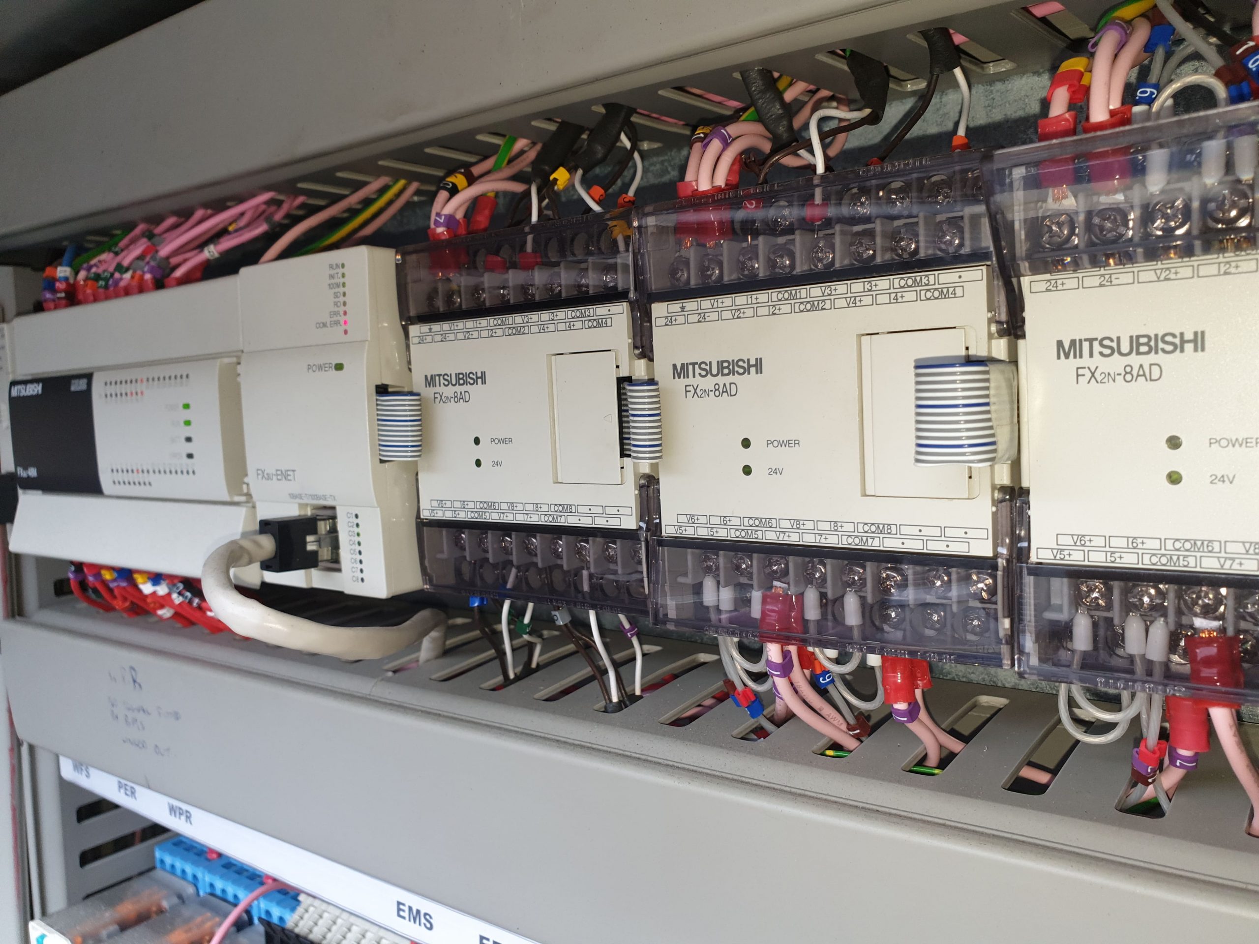
A chiller service company can carry out electrical testing and diagnosis even when a wiring diagram is not available- our engineers can trace the wiring around a chiller.
News Article No.3
Doing this often aids with the diagnosis even when there is a wiring diagram, as having your eyes on a component often makes more sense than a symbol. In any case, our engineers carry out system testing with Fluke multimetes and ammeters.
F-gas Leak Testing by Chiller Service Company
We also carry a range of thermocouples and probes to be used in conjunction with our calibrated digital thermometers. We use these along with comparators to carry out leak testing. After fitting the probes, we first have a visual look around for a sign of a gas leak. All parts of the pipework and system components are inspected. Then, we carry out a full refrigerant diagnosis to determine that the refrigerant system is operating with a full charge. Reports for each chiller are completed and filed in the onsite F-gas leak register. A history can be built up to assess the serviceability of the plant and the frequency of any leaks.
Chiller Service Company Monitoring
Where intermittent faults are concerned, on site monitoring is required. If the job is not progressed on each visit, there is little point in a call out. We carry out tests during monitoring and ensure that the wiring is tight. Hopefully, waiting for the fault to occur whilst next to the machine. Alongside this, we rely on feedback from the end user, as regards, the symptoms and the circumstances of the chiller when the fault occurred. From this we extrapolate the diagnosis and decide the next step to take. This may be to attempt to move the fault to another machine or, at least eliminate one thing each visit.
0161 237 3727
service@maximuschillers.com
Chiller Service Company Evaporators
Shell and Tube
These have a rolled steel shell, welded down the seam with and end plate on either end. The water system pipes can be bolted to the sides or the end. The endplate can be removed for access to the waterside of the tubes. A strainer is fitted to the inlet to catch any foreign objects that may have been carried around the water system. Inlet and outlet gauges are fitted for the monitoring of the water system readings during a visit.
Flooded
On larger chillers, the screw or centrifugal compressor is mounted directly on top of the flooded evaporator. The refrigerant is in its liquid phase on the outside of the tubes. These are arranged in a rack extending through the length of the shell. The warmer process water running through the tubes causes the refrigerant to boil off. A sight glass is usually available to check the state of the refrigerant evaporating on the copper tubes. The suction from the top of the evaporator goes round a baffle so as to prevent the slug back of liquid refrigerant into the compressor. The refrigerant flow into the evaporator is controlled by the expansion valve…
Expansion Valves
This takes the form of a fixed size orifice on the liquid line in between the shell and tube condenser and the flooded evaporator. The size of the orifice previously being calculated to match the mass flow rate of the refrigerant dictated by the compressor. Some newer systems have a variable orifice for the more efficient running of the plant. This is controlled electronically along with the loading of the compressor, relative to the available load.
Multiple System N+1
Smaller DX evaporators are usually multi system. This gives an N+1 redundancy of the plant. Indeed, when one side of a 2 system evaporator is having service work carried out, the other side continues to operate normally. Thinking ahead and allowing for additional capacity is essential when the application is critical, such as, a data centre or a hospital. When a redundant system comes online due to a failure- getting the failed system back up and running is a matter of urgency. For this we offer same day delivery of parts and a fully stocked mobile workshop.
0161 237 3727
service@maximuschillers.com
Chiller Service Company Condensers
Various configurations are employed to ensure good air flow through the condenser fins. The most popular being a ‘v’ condenser as the surface area is increased with this design. Powerful fans are used to reject the air and heat upwards and away from the chiller. Where system location causes the recirculation of air, duct work can be fitted to direct the air away from the chiller. The pressure is monitored using a HP gauge.
Pressure Transducers
Johnson Controls
A popular kind of pressure transducer that is used on condensers is Johnson Controls. These can be bolted onto the refrigerant discharge pipe to sense the system pressure. They have a 5vdc input that comes into the transducer on a red wire, a black wire is the ground and a white wire is the signal back to the fan speed controller. The transducer has a minimum to maximum range, so a chart can be used to determine if the signal is reading back correctly. On chillers where the transducer is wired directly in the controller- calibration can be carried out to offset the readings.
Keller
Another kind of pressure transducer is the 4-20mA type. It sends a mA signal back to the controller or the fan speed controller. 4mA is the minimum position, so this relates to the minimum of the transducer pressure range.
R134a Refrigerant
R134a refrigerant operates at a lower pressure in a condenser than the other commonly used HFC refrigerants. If you were looking for a chilled water set point of 6°C in the UK ambient for example, the R134a refrigerant saturation on the high side of the system would be around 36°C Latent heat from the water system and heat added into the refrigerant from the compressor are rejected from the condenser. As the refrigerant passes down the condenser tubes, cool air blowing across the outside of the tubes, cools the refrigerant vapour down through the latent heat phase and into a subcooled liquid.
0161 237 3727
service@maximuschillers.com
Chiller Service Company Compressors
Centrifugal Compressors
This kind of compressor has a lower volumetric efficiency compared with the positive displacement compressors below. This is because the refrigerant is compressed using centrifugal force off the tip of the impeller, instead of being mechanically compressed. The advantage of this kind of compressor is a high mass flow rate of refrigerant. These compressors are used in factories where a large amount of chilled water is required to cool the process. They are also used in countries where district cooling is used. The chillers are arranged in rows in a chiller hall and are piped into the district cooling loop.
Screw Compressors
Oil used to lubricate the bearings is also used to create a seal between the rotors. Computer aided design (CAD) software and computer numerical control (CNC) grinding machines are used in the construction of screw rotors. The shape of the rotors is designed to compress the refrigerant along the screw. The length of the screw that is available to compress the refrigerant can be adjusted with a slide valve. Any stage of loading between 0- 100% can be achieved. This is regulated with a slide valve potentiometer. Screw compressors are very reliable and have a long service life. They also have a low vibration reading which ensures a lower instance of refrigerant leaks around the compressor.
Scroll Compressors
A service free compressor. Service free assuming that the rest of the system is functioning correctly. This kind of compressor relies on oil migration around the system. The oil is entrained along the inside of the pipework, around the system and back to the compressor. An oil level sight glass is fitted into the body of the compressor at the required level. Refrigerant shortage can cause the oil to stay in the bottom of the evaporator, causing a low oil level condition in the compressor. We can be scheduled to attend site to drain the oil, then pump new oil into the compressor.
Compressor Failure
When any of the above compressors fail, you are in safe hands with Maximus Chillers. We have the capability to lift and shift the compressor to our remanufacturing facility for a full overhaul. The reason for the failure is diagnosed to ensure the new compressor does not fail for the same reason. Improving the reliability of your plant and extending its life is what we are all about- if we can reduce your service costs- that makes us happy! All temperatures and pressures are recorded to ensure the replacement compressor goes into seamless operation.
Any Chiller- Any Problem- Any Part- Any Refrigerant- Anywhere- The MAXIMUS ADVANTAGE™
Related Articles:
Chilling Plant Service
Chilled Water System EEV Service
Water System Service of Evaporator
Process Chiller Vacuum Service
Chiller Fault Finding & Diagnosis
Air Cooled Chiller Condenser Testing
To read more about chiller diagnosis hit the Tag below.
Read more about pressure sensors on Wikipedia