On an industrial chiller service visit, the ammonia alarm was found to have been triggered.
News Article No.10
Industrial Chiller Service Faults
The onsite engineer had fault found the chiller and silenced the alarm, the yellow light was still flashing. The red light was lit on the panel and the red LED was illuminated on the ammonia alarm console. He had reported a smell of ammonia to us over the phone. This gave us a priority of getting to site, as many other alarms of this nature are often spurious. Our engineer attended site within an hour and confirmed that the fault finding was correct as described by the onsite engineer. The chiller is containerized in design as it is situated outside. All around the chiller are door panels for access to the various system components.
Breathing Apparatus and PPE
He donned his mask and full length ammonia resistant PPE before opening one of the panel doors. This was to ensure that he did not get overwhelmed by the refrigerant when he opened the door. He started with the door into the storage area of the containerized chiller. A strong blast of ammonia came out in his face- lucky for the PPE!
Localising the Fault
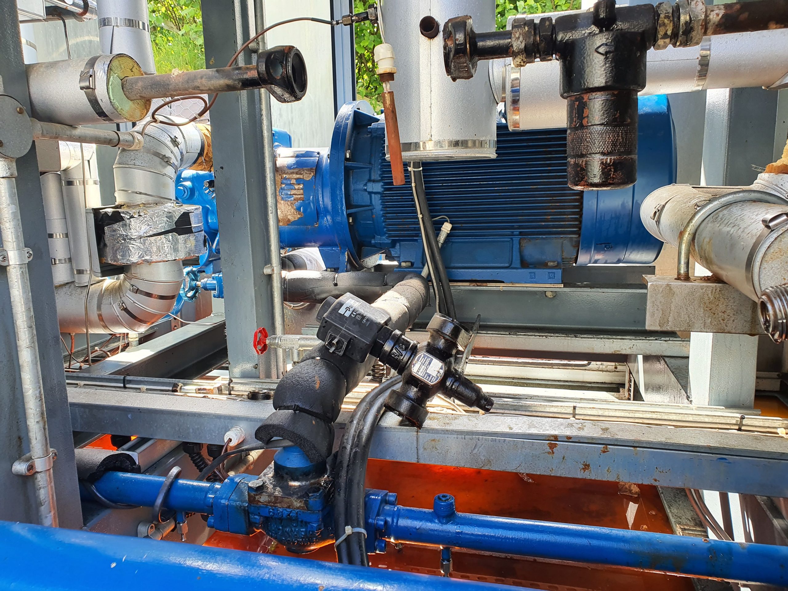
Working his way around the chiller, our engineer found more and more hazardous door openings! Eventually he found the culprit: one of the two flanges were leaking on the oil return solenoid. The refrigerant vapour was coming out in its usual white form. The oil return pipe feeds off the oil pot which is a chamber that the oil sinks into from the refrigerant economizer. This vessel was valved off and the other end of the pipe valved off too.
Pinpointing the Fault
Now that the ammonia refrigerant leak had started to calm down- it was possible to see through the white vapour to exactly which of the flanges was leaking. It was the right one as seen in the picture. It consists of an ‘o’ ring made of ammonia resistant rubber material.
0161 237 3727
service@maximuschillers.com
Industrial Chiller Service in Local
The above mentioned chiller runs in local in a lead/ lag configuration with the adjacent chiller. That is to say- there is no wire or modem to a remote location. A panel is available in between the two chillers to sequence the switch over between the two. When the chiller tripped out due to the fault, the other chiller was supposed to have been enabled. This did not happen, so our engineer investigated the situation. The sequencer panel sends out a 24v fault feedback signal to each chiller. This, in turn, goes through a relay and back to the sequencer panel if all is good. When a fault occurs, the volts drop out to the relay in the chiller and a relay drops out in the sequencer. When the relay drops out in the sequencer, a normally closed contact makes and brings a red light on. This was not happening, so our engineer followed it through with his multimeter. He found a blown 1 Amp control fuse in the chiller, he replaced it and it blew again. After some careful research he found that there was an earth leakage due to the ingress of water into a safety switch. This switch was nothing to do with the above, but it blew the whole control circuit. Having reinstated the fuse, he found that the panel switched over satisfactorily in local.
Advantages
This kind of operation method has an advantage in its simplicity. There are no complicated BMS systems for the chiller to be integrated into. A sequencer panel is easy to construct and maintain- keeping the costs down to the end user.
Disadvantages
The disadvantage of this kind of system is that the first thing the factory usually notices is that they are loosing the process. The water temperature getting too high is the first alarm signal. With this site, however, there is a permanent onsite engineer on hand. He is experienced with the first checks to carry out and can often get the plant running with no problem.
0161 237 3727
service@maximuschillers.com
Standing Pressure during Industrial Chiller Service
The standing pressure was taken into account on the return visit to fit the oil return solenoid valve seal. Because the valve is on the low side of the system, when the chiller is off, the pressure is higher than when it is on. Therefore, so long as the seal pressure tests to this pressure, then all will be good when the system is running. That is assuming that the valve seals work satisfactorily at a lower temperature range. There are issues sometimes when a seal will be okay at ambient temperature but will leak when it becomes brittle at a colder temperature. This happens usually on an old seal and, indeed, this condition can be tested for when run testing the system.
Leak Testing during Industrial Chiller Service
On fitting the seal, our engineer donned full length ammonia resistant PPE and breathing apparatus. A little at a time, he introduced refrigerant into the area of the valve seal. Any residual air being purged through a valve.
Pressure and Temperature
The standing pressure of refrigerant is affected by temperature. That is to say- that the higher the temperature- the higher the pressure. On the day this job was carried out, the ambient temperature was 12°C and using an app on his phone, he calculated that the pressure should be 5.6bar. This is consistent with Charles’ Law of Constant Volume with a coefficient added for this particular refrigerant. If the pressure had been higher than this, it would indicate the presence of air in the system. Daltons’ Law of Partial Pressures states that all gasses in a vessel will act as if they are on their own, therefore, causing a higher pressure.
Run Testing during Industrial Chiller Service
After the pressure was built up to full standing pressure and the seal held satisfactorily, the system was then run tested to ensure, as stated above, that the seal performed well across the full temperature range during the operation of the plant.
0161 237 3727
service@maximuschillers.com
Mass Flow Rate during Industrial Chiller Service
The mass of refrigerant passing, which is measured by the second.
Suction Density
In this case of the oil return valve seal, we are looking at the density of the low side refrigerant as it passes into the suction port of the compressor. This is shown on the LP gauge near to the compressor. The higher the pressure of the refrigerant, the more refrigerant there is- so it has a higher mass flow rate. This system has a refrigerant saturation point of 1°C which corresponds to a pressure 3.4bar. That is a high mass flow rate for this kind of refrigerant. This is because this refrigerant is usually used in low temperature applications where the pressure of the refrigerant is below that of the atmosphere. In that condition, when a leak occurs on the low side of the system- air leaks in. Air bleed valves are available to remove this unwanted air from the system.
Compressor Loading
The bigger the compressor on a chiller- the higher the mass flow rate. Most compressors have loading solenoids, vanes, or a slide valve to regulate this.
Piston Displacement
Reciprocating compressors use loading solenoids to increase piston displacement. Usually, oil from the oil pump holds the piston valves open and so preventing compression on that cylinder. When more flow rate is needed- the loading solenoid de energizes- the piston valves drop and the cylinder comes into action. Therefore, increasing the mass of refrigerant through the compressor.
Vanes
Vanes are used on centrifugal compressors to increase the flow of refrigerant through the compressor. An actuator linked to a chain is used to open the vanes. The controls work out the correct position of the vanes for a given load condition.
Slide Valve
The slide valve offers a seamless amount of loading, anywhere between 0% and 100% A slide valve potentiometer senses the position of the slide so that the controls can regulate the flow through the compressor. The screw compressor in this article uses a slide valve- on full load with the slide at 100% all readings were taken with a good read back. Another job done- another happy customer!
Related Articles:
Chilling Plant Service
Chilled Water System EEV Service
Water System Service of Evaporator
Process Chiller Vacuum Service
Chiller Fault Finding & Diagnosis
To read more about chiller fault finding hit the Tag below.
Read more about refrigerant mass flow rate at Science Direct